Overview
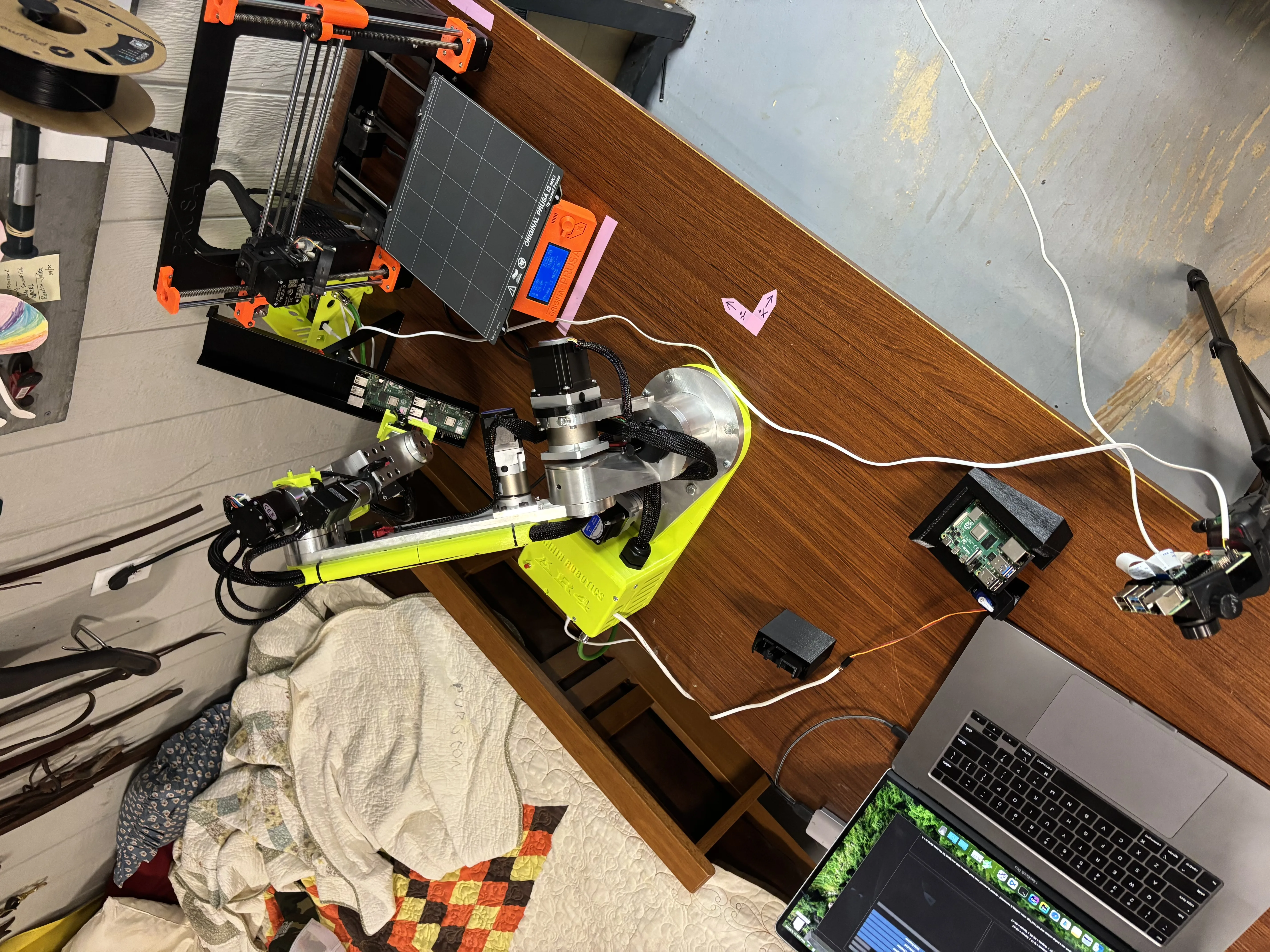
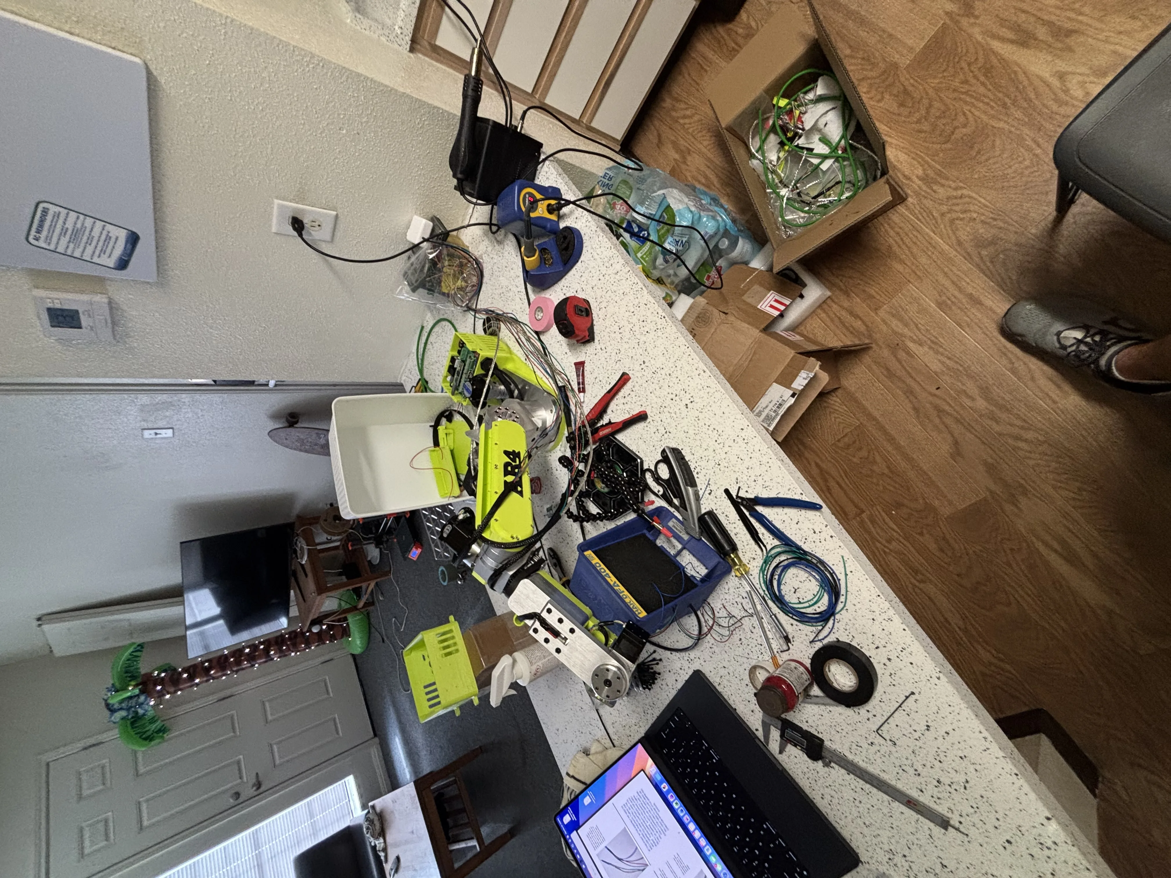
In late 2025 I purchased and assembled an AR4 robot to use in various projects. While it can read digital pins and communicate over Modbus, I was interested in a more customizable solution that could send AR4 programs to the robot as well as control other equipment. I created this orchestration software over the course of about a week and a half. This post will explain how it works and the decisions I made while creating it.
The design
Setting some quick goals, I wanted the new software to be in charge of decision-making, in most machine-tending setups the machine is in charge of the robot and in some rare cases the other way around. I chose to make orchestration software because neither my Prusa I3 nor the AR4 control are capable of the versatility I was hoping to achieve. While my software has minimal options, I feel it is actually quite flexible since it simply inputs the two machines’ native files.
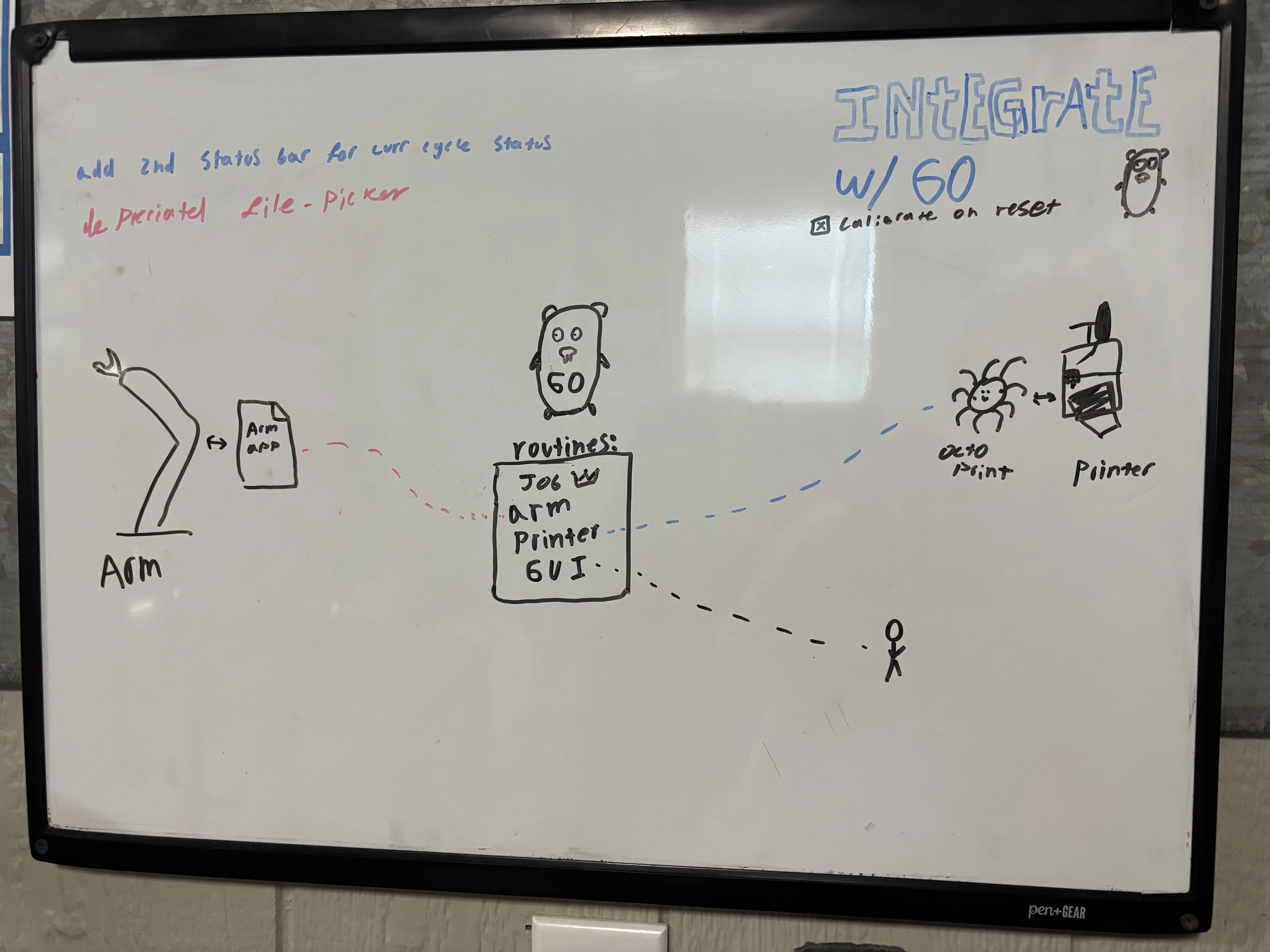
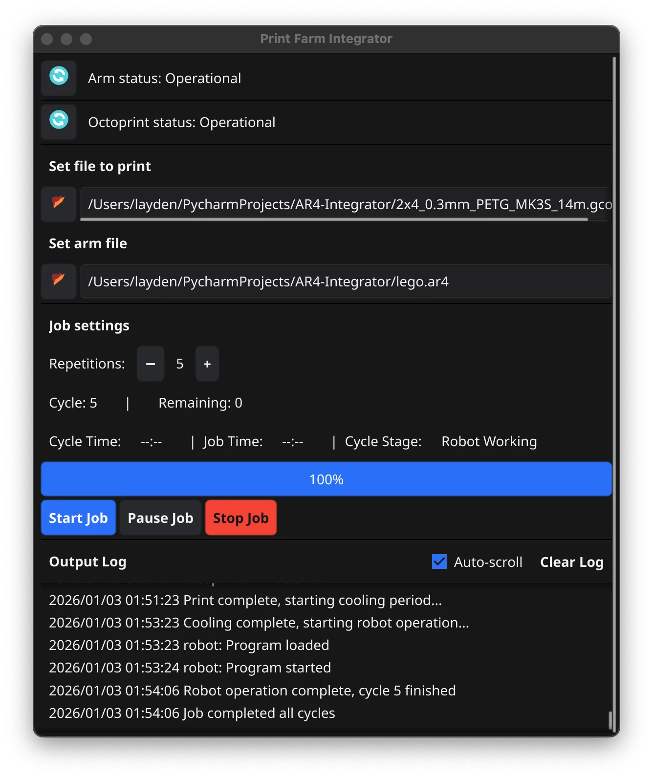
The GUI is made of four panels, The first manages the interfaces to the robot and Octoprint. The second manages the .ar4 and .gcode files being sent to the robot and printer respectively. The third panel lets the user set how many times the programs should run as well as job status and controls like start, stop, pause. Finally, the last panel shows an auto-scrolling log of the program output.
Interfacing with the machines
AR4 control
The AR4 is run similar to other robots where positions are captured then organized in a program, in this case the .ar4 file. But unline the others, the control software is written primarily in one almost 16,000-line single-threaded Python script. I forked this project to run it on an Intel-MacBook, the changes I made were to slim it down mainly by removing large libraries that were no use to me like OpenCV. To handel the integration, I added a TCP server that allows request to be made to the control software. Commands include get status, load program, goto line, start, stop, and calibrate. I plan on changing this API to be a websocket in the future to better track connection status or a software crash.
3D printer
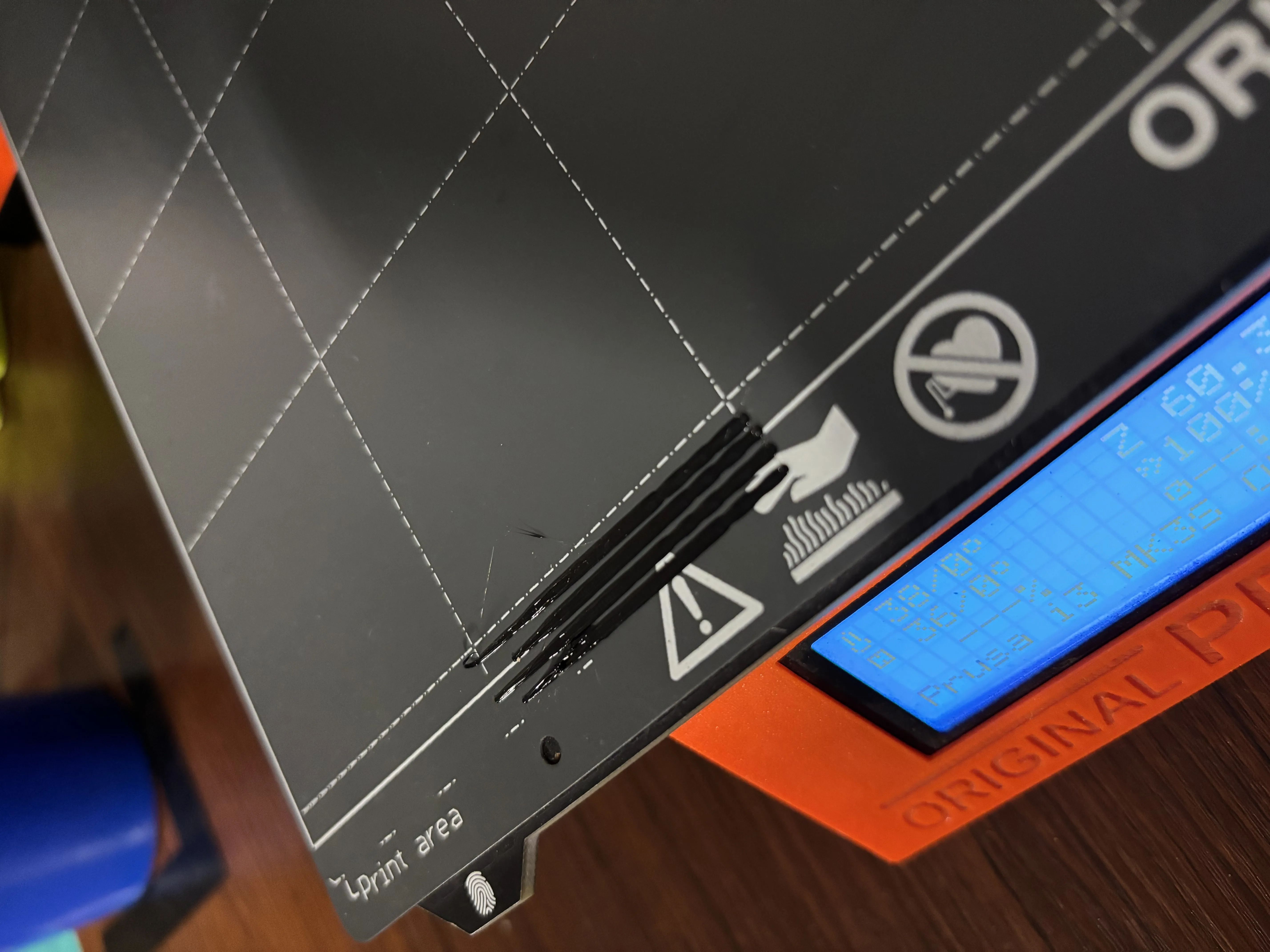
The 3D printer is a Prusa I3 MK3S controlled by Octoprint. Initially I tried to drip-feed the printer Gcode for closer control over it, but it proved to be very finicky. Once I realized I was essentially trying to make a USB driver, I decided to instead implement the Ocotprint API into the printer handler. I also ran into some Issues with Octoprint’s security but resolved them by simply running the server on the same machine as the orchestrator. Finally, I also had the forethought to preprocess the Gcode to offset the nozzle’s purge line by a small amount after each cycle.
Orchestration software
The software I created spawns three Goroutines (threads) that handle the various components simultaneously and communicate through channels. There are handlers for the printer, robot, and job queuing; then the original thread handles the GUI. The Job handler runs a ticker that cycles a control loop every 100ms. The control loop reads the state channels to determine the next step in the cycle and dispatches commands to the machine handlers and GUI. Each of the machine handlers essentially is a wrapper for its respective API. They are separated into modules for readability since making all of those requests can get lengthy. The machine handlers are also responsible for detecting, starting, stopping, restarting the external software, including OctoPrint and the AR4 control.
E stop scenario
The E-stop is wired to a robot digital input read and handled by the AR4 control, then automatically communicated to the job handler. At no point does it cut motor power; instead, it halts motion commands and holds position to avoid secondary crashes since the robot lacks motor breaks. This is not something I would implement in an industrial setting, but due to the low-stakes nature of this project, I decided to let it be. In its current configuration on an E stop, the Job handler will command the printer to stop and park instead of resetting it or even cutting power completely.
What I learned from phase 2
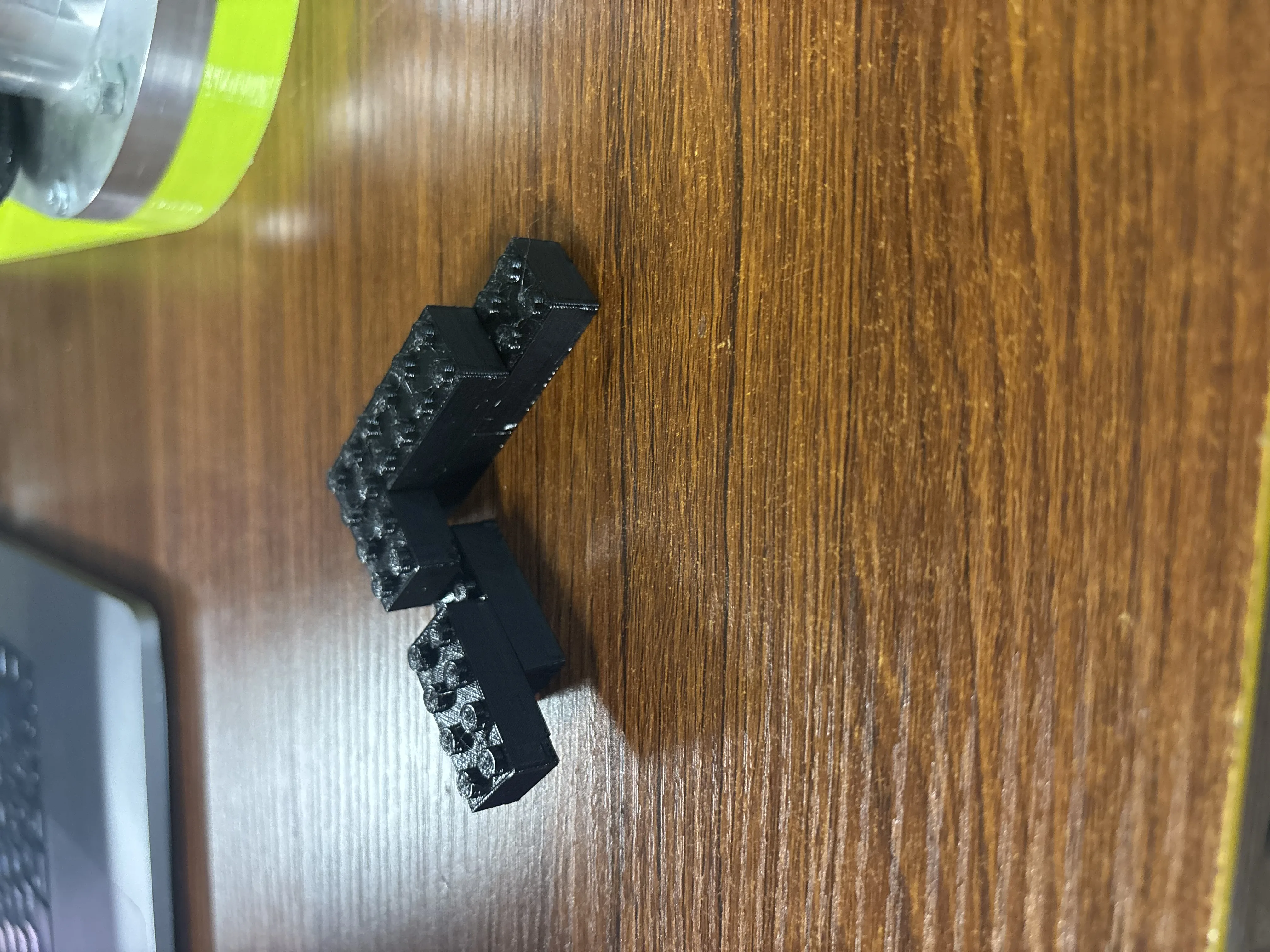
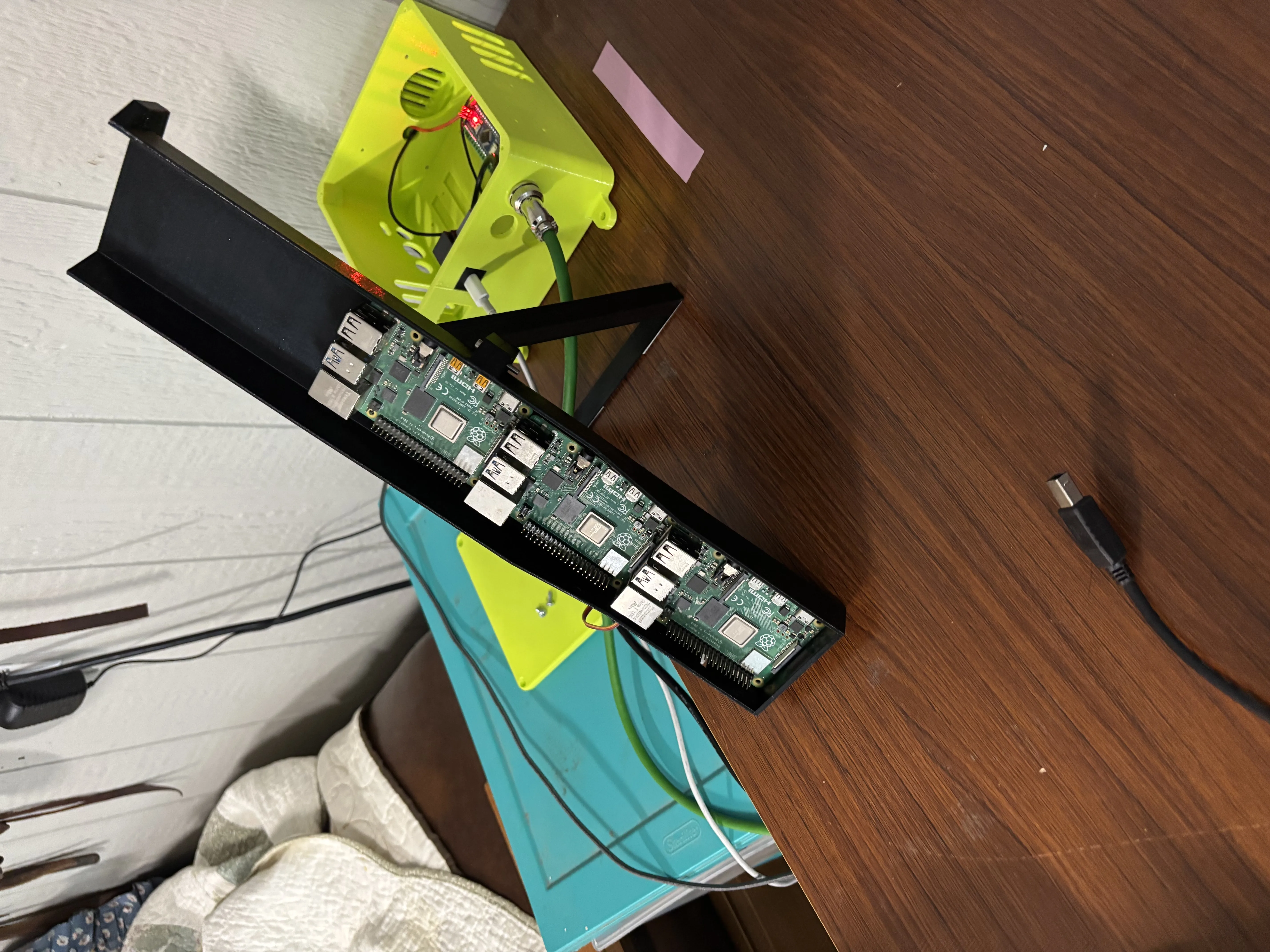
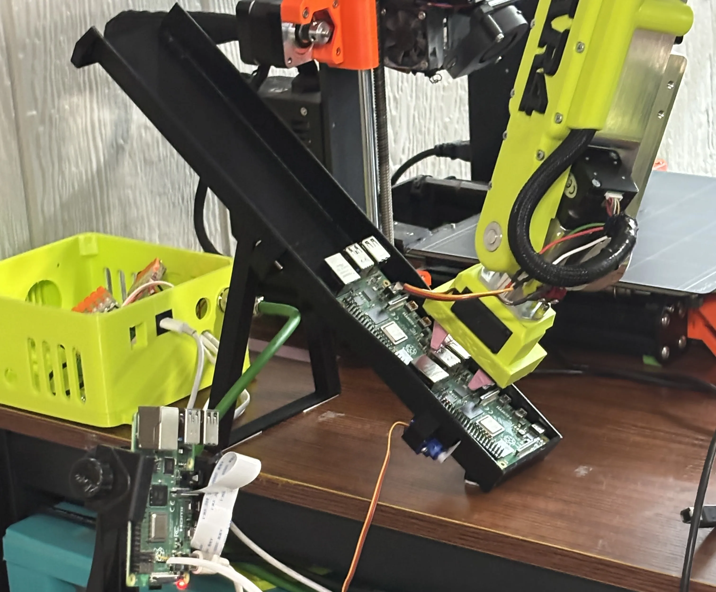
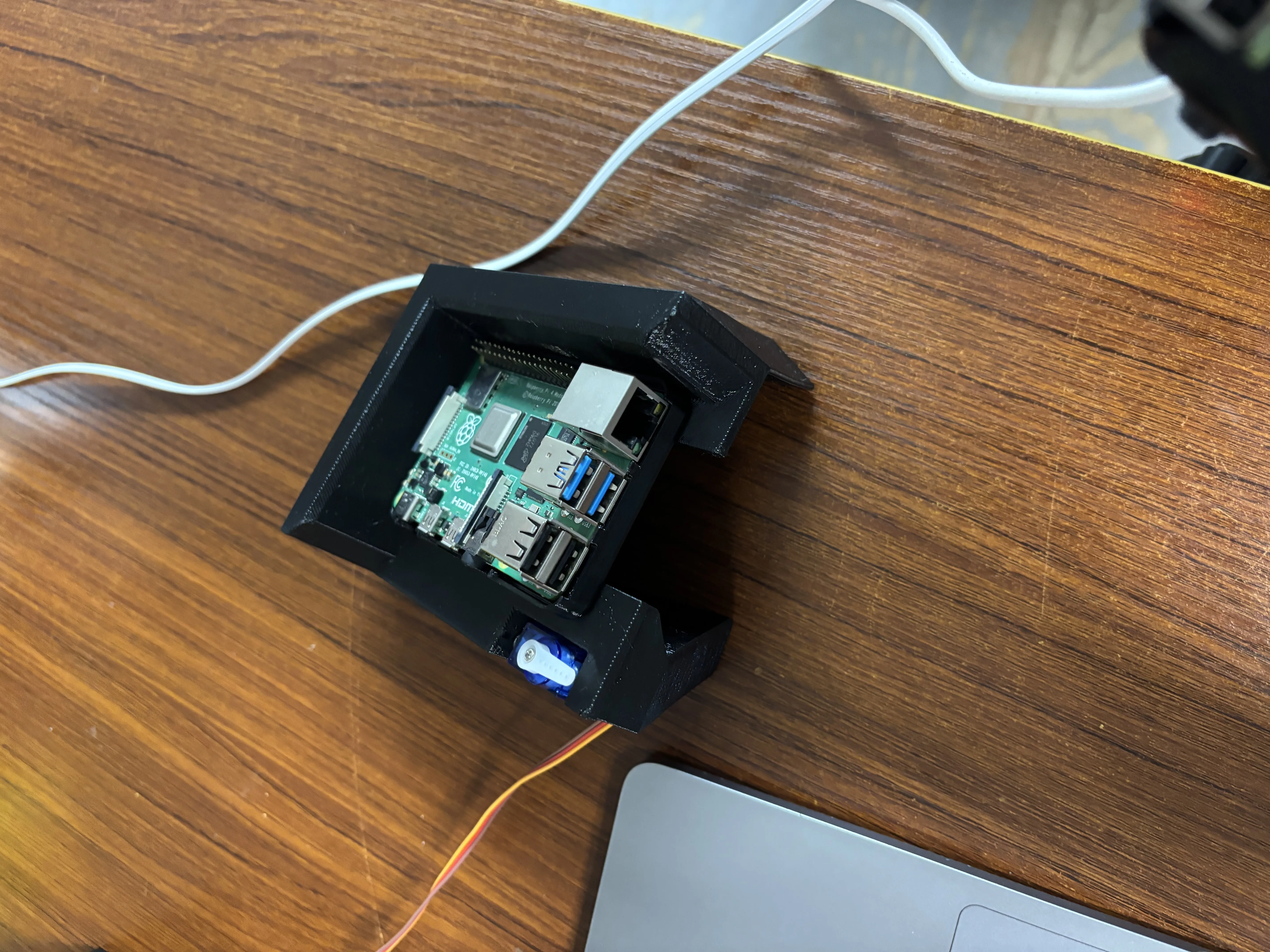
I challenged my self to make a cell that could print and RPi case and place an RPi in it and snap it shut. This project did not succeed but did help me understand the limits of the robot. I made fixtures for the RPis and cases, but fighting the lack of a custom end effector and poor precision of the robot, I decided to abandon the challenge.
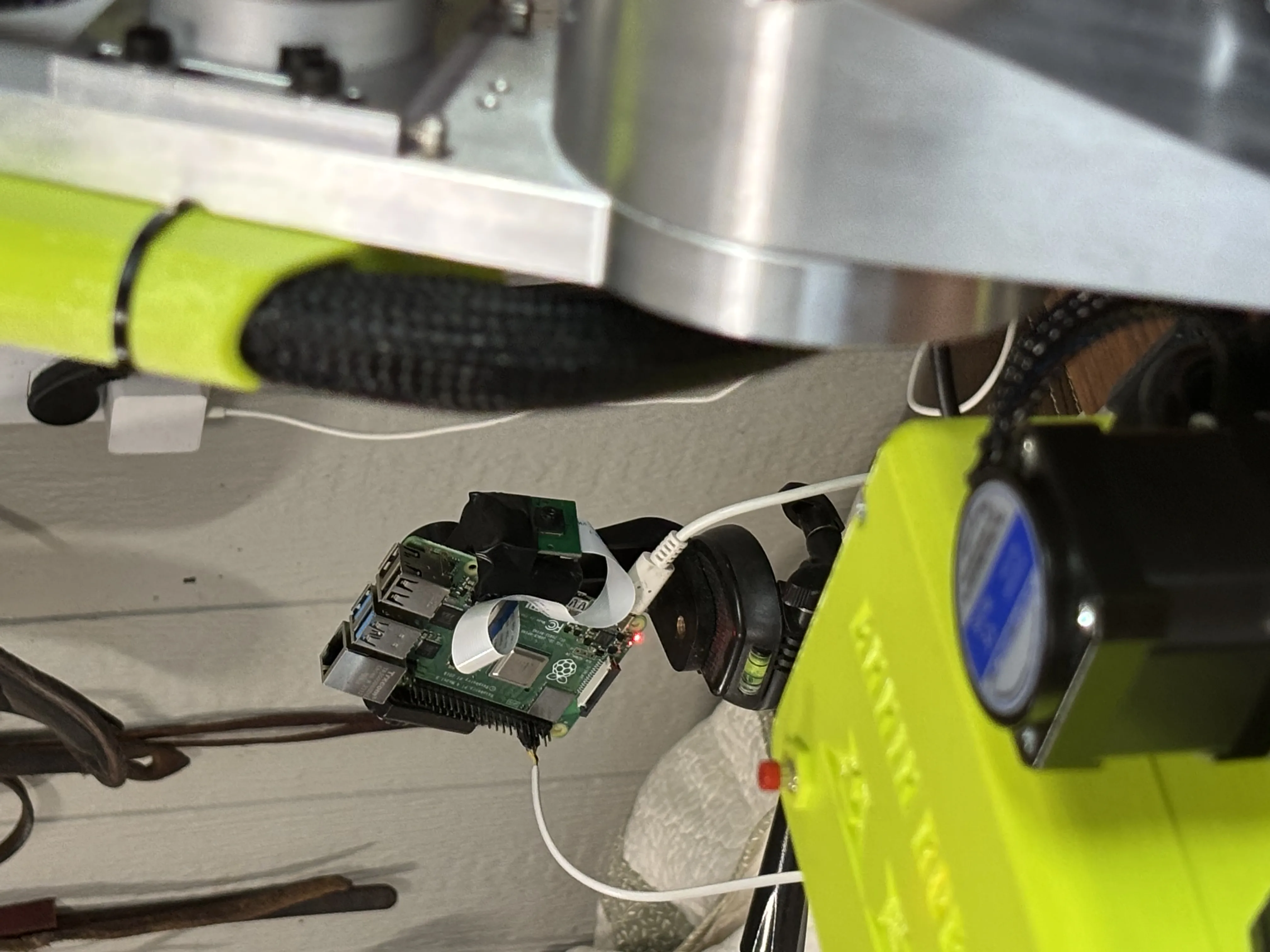
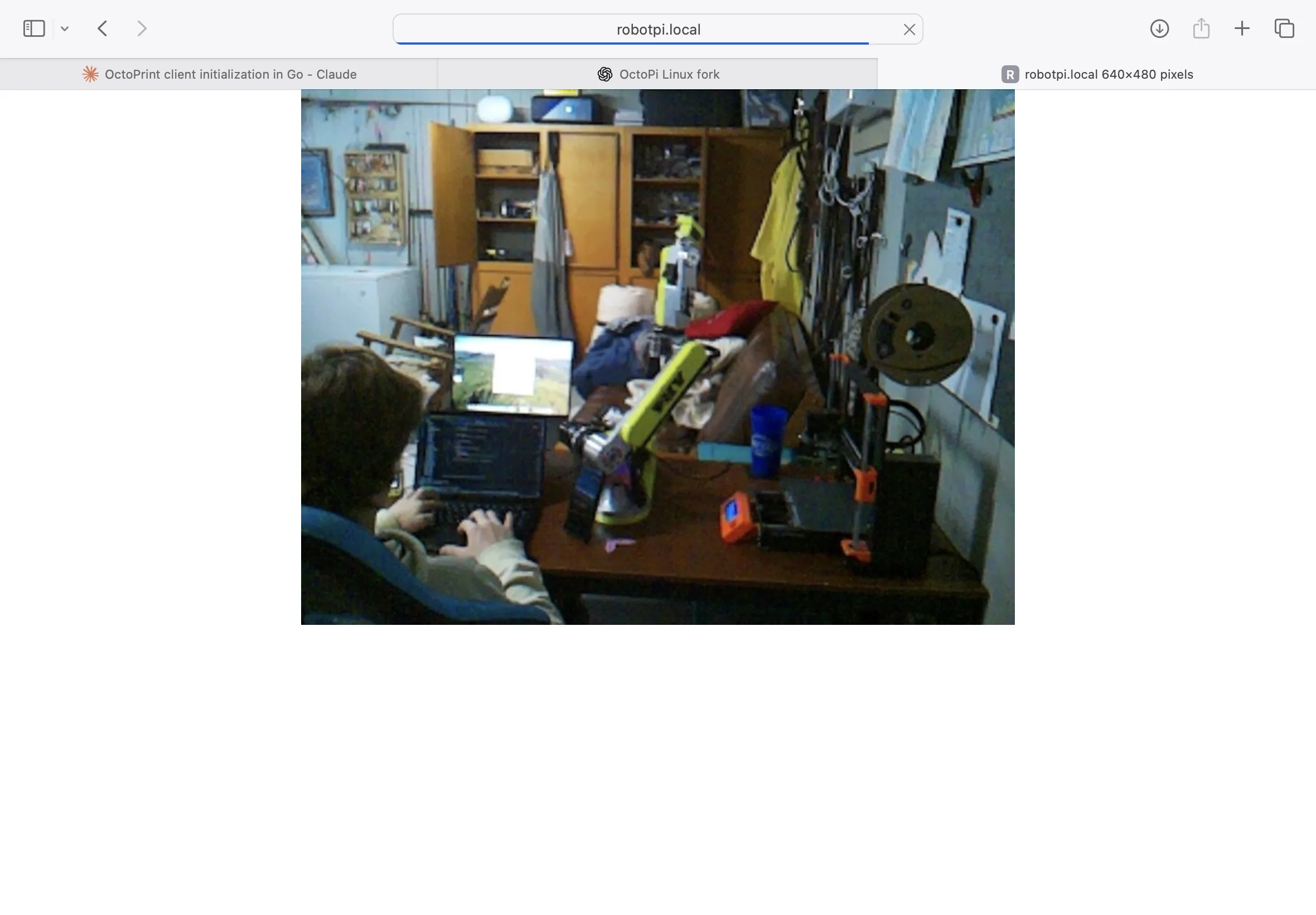
During that development I gave the robot a third-person RPi camera that could be triggered as a part of its program, so when it moved to a position, I could have a folder of pictures to see how it preformed over time. I ran some experiments and realized this robot is different from most. It is similar to a CNC machine since it needs to home its axis on startup. Most industrial robots have “mastering” where they remember their position with the battery’s powered memory; most robots don’t even have limit switches for the use of homing.
Moving forward
Those familiar with the AR4 community and modern educational/research robotics will know that ROS2 may have been a more ideal solution. I’m currently working towards getting that set up, and I would’ve used ROS2 in the first place If I had known how common it was. I was drawn to this approach because it seemed a quicker timeline to get all the pieces working together. Nevertheless, I’m looking forward to using ROS2 In my AR4’s next project. I’ve got a job in mind for it and a new end-effector design coming.